
TM 9-2320-280-34
12-16. DIFFERENTIAL SUPPORT BRACKET AND SIDE MOUNTING BRACKET
REPLACEMENT (Cont'd)
b. Installation
NOTE
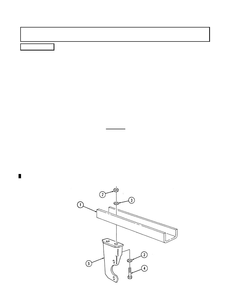
New configuration side mounting bracket allows for output shaft
seal replacement without bracket removal. If old configuration
mounts were removed, installation of new configuration side
mounting bracket is recommended.
1.
Install side mounting bracket (5) on support bracket (1) with two washers (3), capscrews (4),
washers (3), and locknuts (2).
2.
Install differential support bracket (1) and differential side mounting bracket (5) on suspension
crossmember (12) with two washers (7), capscrews (8), washers (7), and locknuts (9).
3.
Align holes inside mounting bracket (5) with threaded holes in differential (6).
4.
Remove two locknuts (9), washers (7), capscrews (8), washers (7), side mounting bracket (5) and
support bracket (1) from crossmembers (12).
Tighten capscrews (4) to 90 lb-ft (122 Nm).
5.
6.
Install support bracket (1) and side mounting bracket (5) on crossmembers (12) with two
washers (7), capscrews (8), washers (7), and locknuts (9).
CAUTION
Apply a liberal amount of thread sealing compound to the tapped
holes of differential. To allow adequate coating of threads, install
capscrews shortly after applying thread sealing compound. Failure to
do this could allow capscrews to loosen and cause damage to
differential.
7.
Apply sealing compound to tapped holes of differential (6). Install two short capscrews (10) and
washers (11) securing side mounting bracket (5) to differential (6). Tighten capscrews (10)
to 110-140 lb-ft (149-190 Nm) and capscrews (8) to 90 lb-ft (122 Nm).
8.
Apply sealing compound to tapped holes of differential (6) and install brake adapter (17) on
differential (6) with two capscrews (18). Tighten capscrews (18) to 110-140 lb-ft (149-190 Nm).
9.
Install output flange (14), two O-rings (15), and locknut (16) on output shaft (13). Tighten
locknut (16) to 170 lb-ft (231 Nm).
Change 2
