CHAPTER 17
REPAIR OF THE TRANSFER CASE ASSEMBLY
17-1. Disassembling, Cleaning, and Inspecting the
Transfer Assembly.
a. Disassembly.
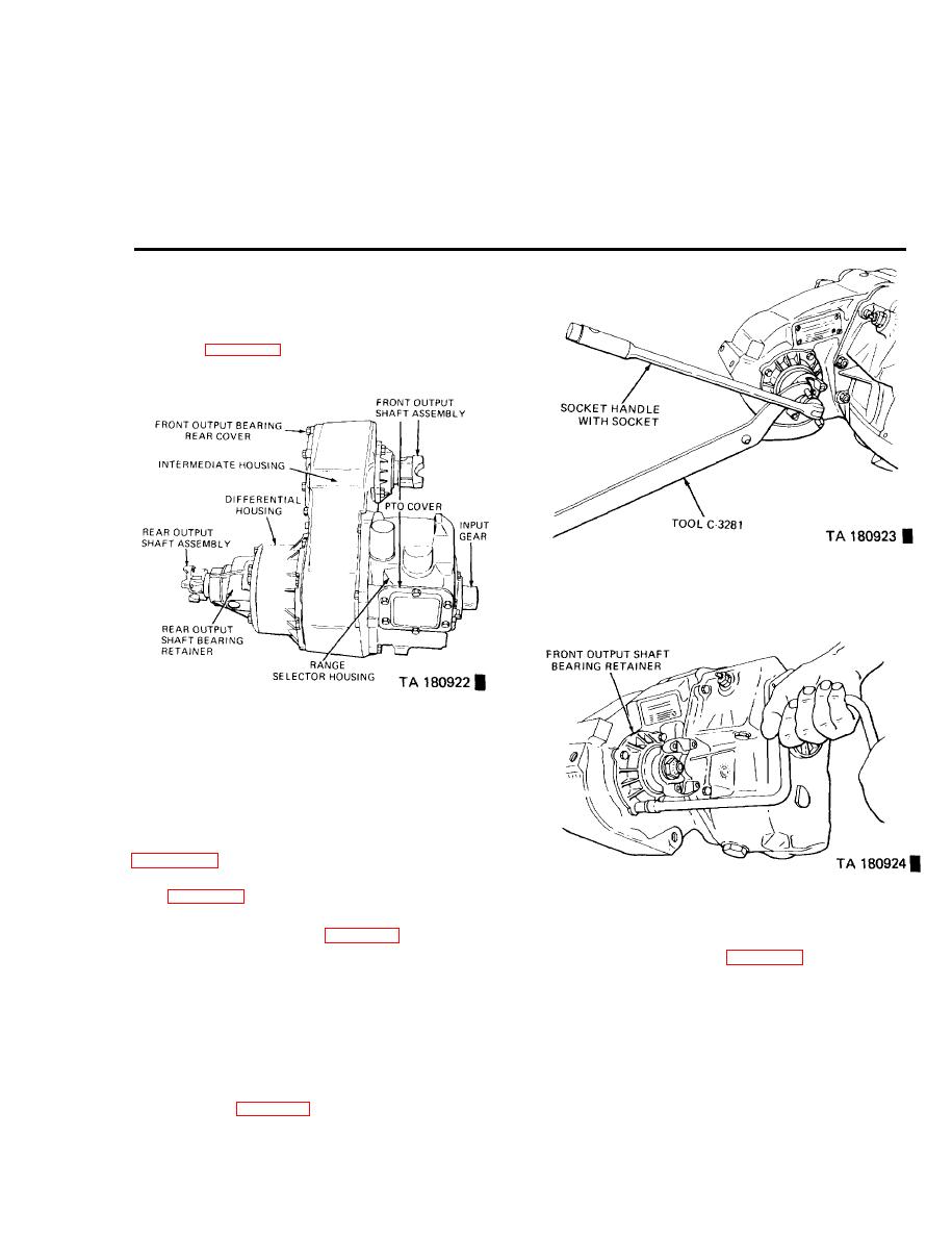
(1) Position the drained transfer case on a suitable
drive gear adapter.
Figure 17-2. Loosening Front Output Shaft Yoke Nut.
Figure 17-1. Transfer Case in Position for Removing
Output Yokes.
(2) Using holding tool C-3281 and a 1-5/16 inch
socket with a suitable handle, loosen the rear output shaft
yoke nut.
(3) Using holding tool C-3281 and a socket with a
suitable handle, remove the front output shaft yoke nut
(4) Remove the front output shaft bearing retainer
Figure 17-3. Removing Bearing Retainer Screws.
bolts (figure 17-3). Remove the retainer. Discard the gasket.
(5) Using a jack or other suitable lifting device, posi-
tion the transfer case on blocks (figure 17-4).
(9) Remove the shift rail detent ball plug, gasket,
spring, and ball from the case (figure 17-6) A small magnet
(6) Remove the differential housing retainer bolts
may be used to remove the ball.
and disengage the assembly from the transfer case. Remove
and discard all gaskets.
(10) Push the Shift rail down, and lift it up on the
lockout clutch. Remove the shift fork from the clutch
(7) Slide the carrier unit from the shaft. A 1-1/2 to
assembly.
2 inch band-type hose clamp may be installed on the input
shaft to prevent losing the bearings when removing the input
(11) Remove the front output shaft rear bearing re-
shaft assembly from the range box.
tainer bolts. Tap on the front of the shaft or carefully pry
the retainer away from the case. Remove the retainer from
(8) Raise [he shift rail and drive the retaining pin out
the shaft and discard the gasket. Recover any roller bearings
of the shift fork. (figure 17-5).
Change 6
17-1


