TM 9-2320-266-34
c. Input Shaft Assembly.
(4) Inspection. Carefully inspect all bearings and
rollers for wear or damage. Use new parts if replacement is
(1) Slide the thrust washer and spacer from the shaft.
necessary. Inspect the shaft splines, drive chain, and gears.
(2) Using the snap ring pliers, remove the retainer
Replace any parts showing wear or damage with new parts.
from the input shaft (figure 17-10).
(3) Tap the shaft out of low-speed gear. Look for the
two thrust-washer pins in the shaft.
(4) With a screwdriver, remove the Iockring out of the
bearing retainer (figure 17-11). Tap the bearing out of the
ret airier bore.
(5) Remove the roller bearings (15) from the end of
the input shaft.
(6) Remove and discard the "O" ring from the end of
the shaft.
(7) Clean and inspect all components. Replace them
if worn or damaged.
17-3. Disassembly of Range Selector Housing
(Range Box).
a. Removing Shifter Shaft Assembly.
(1) Remove the detent plate spring, plug, and gasket.
Discard the gasket.
(2) Disengage the sliding clutch gear from the case.
(3) Remove the shift lever assembly retaining nut and
the range shift lever from the shifter shaft.
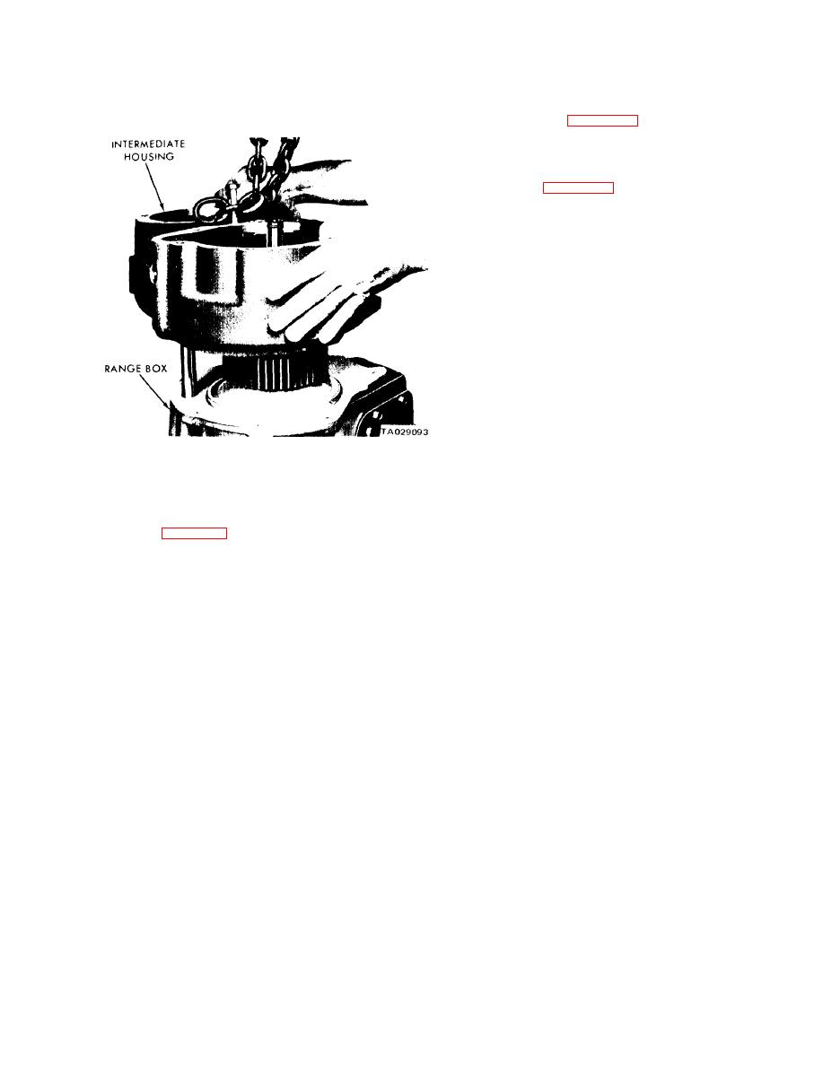
Figure 17-8. Removing Intermediate Housing.
(4) Remove the shift lever snap ring and locknut shift
lever.
17-2. Disassembly of Subassemblies.
(5) Push the shifter shaft assembly down and remove
the lockout clutch connector link. The long end of the con-
Refer to figure 17-9.
nector link engages the detent plate.
a. Differential Garrier Assembly.
(6) Remove the shifter shaft assembly from the case
(1) Remove the bolts from the carrier assembly and"
and separate the inner and outer shifter shafts. Remove and
separate the carrier section.
discard the "O" rings.
(2) Lift the pinion gear and spider assembly from the
(7) Inspect the detent plate for damage. If it is
carrier. See that the undercut side of the pinion gear spider
necessary to remove it, drive the pivot shaft from the case.
faces toward the front side gear.
Remove the detent plate and spring from the bottom of
the case.
(3) Remove the pinion thrust washers, the pinion
roller washers, and the pinion gears and roller bearing from
b. Removing Input Gear Assembly.
the spider unit.
(1) Remove the input gear bearing retainer and seal
(4) Clean and inspect all components. Replace all
assembly. Discard the gasket.
worn or damaged parts.
(2) Remove the snap ring from the outer diameter of
b. Lockout Clutch Assembly.
the input gear bearing.
(1) Remove the front side gear from the input shaft
(3) Tap the input gear and bearing from the case.
assembly. Remove the thrust washer, roller bearings (1 23),
(4) Remove the bearing retaining snap ring from the
and spacers from the front side gear bore. Note the position
input shaft. This is a select fit snap ring. Use sizes A, B, C,
of the spacers to facilitate reassembly.
or D to provide the tightest fit when reassembling.
(2) Using the snap ring pliers, remove the drive
c. Removing Countershaft Gear Assembly.
sprocket-to-clutch assembly retaining ring. Slide the drive
(1) From the intermediate case side, remove the
sprocket from the front side gear.
countershaft from the countershaft gear and case. Remove
(3) Remove the lower snap ring.
the countershaft gear assembly from the case. Recover 72
(4) Remove the sliding gear, spring, and spring cup
roller bearings from the gear case and shaft.
washer from the front side gear.
(2) Remove the countershaft gear thrust washers
(5) Clean and inspect all components. Replace all
from the case.
worn or defective parts.
17-3


