TM 9-2320-266-34
(8) Put the starter-solenoid return spring into the
bore of the movable core. Inspect the condition of the
starter solenoid switch contacting washer. If the top of the
washer is burned from arcing, disassemble the contact
switch plunger assembly and reverse the washer.
(9) Install the solenoid contact plunger assembly
into the solenoid. Make sure the contact spring is
positioned on the shaft of the solenoid contact plunger
assembly.
(10) Assemble the battery terminal stud in the brush
holder. Inspect the condition of the contacts in the brush-
holder plate. If they are burned, replace the brush holder
with brushes and contacts as an assembly.
(11) Position the seal on the brush-holder plate.
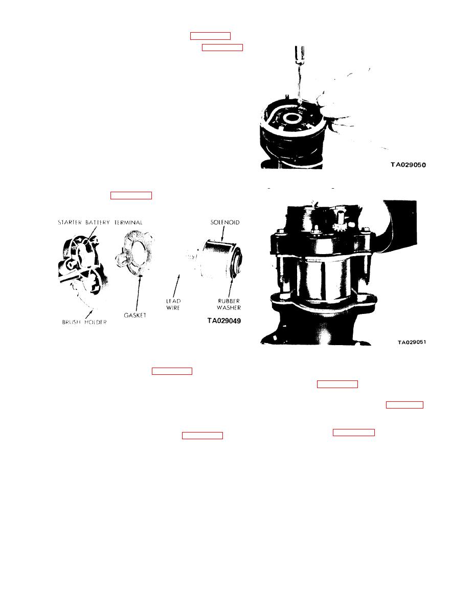
Figure 15-23. Soldering Solenoid Lead to Brush Terminal.
(12) Put the solenoid lead wire through the hole in
the brush holder (figure 15-22) and install the solenoid
stud, the insulating washer, and the washer and nut.
Figure 15-22. Assembling Solenoid to Brush
Holder Assembly.
(13) Wrap the solenoid lead wire tightly around the
Figure 15-24. Installing Solenoid and Brush Plate Assembly.
brush terminal post as shown in figure 15-23 and solder it
(16) Position the brushes with the armature thrust
securely with a high temperature resin core solder and
washer as shown in figure 15-25. This will hold the brushes
resin flux.
out and facilitate proper installation of the armature.
(14) Attach the brush holder to the solenoid attaching
screws.
(18) Position the field frame to the exact position on
(15) Place the solenoid coil and the brush-plate
the gear housing and put the armature into the field frame
assembly into the bore of the gear housing. Place the brush-
and starter gear housing (figure 15-26). Rotate the
plate assembly in the starter gear housing (figure 15-24).
armature slightly to engage the splines of the shaft with
Install the housing attaching nuts and tighten.
the reduction gear.
15-7


