TM 9-2320-266-34
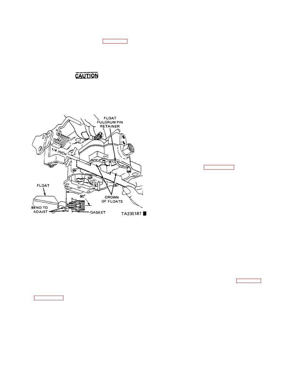
(4) Using a straightedge scale, check the float setting.
(9) Slide the shaft of the accelerator pump lever
The measurement from the top surface of the fuel bowl to
through the rod lifter and the pump arm.
the crown of each float at the center (figure 12-11) should
(10) Install the two locks and the adjusting screws,
be one-quarter inch.
but don't tighten them.
(5) If an adjustment is necessary, hold the floats on
(11) Install the accelerator pump arm so that the
the bottom of the bowl and bend the float lip toward or
operating "S" link is in the outer hole.
away from the needle. Recheck the setting again. Then
(12) Install the fast idle cam and linkage, and tighten
repeat the lip bending operation as required.
the retaining screw.
(13) Connect the accelerator pump linkage to the pump
Do not apply pressure to the float. If the
lever and throttle lever and install the retaining clip.
synthetic rubber needle valve tip is com-
e. Choke Vacuum Diaphragm. Make sure the diaphragm
pressed too much it can cause a false
vacuum fitting is not plugged with foreign material. Check
setting and will affect the correct level of
for internal leaks by depressing the diaphragm stem and
the fuel in the bowl.
putting your finger over the vacuum fitting to seal the
opening. Then let go of the diaphragm stem. If it moves
more than 1/16-inch in 10 seconds, the assembly is leaking
excessively and must be replaced. To install a new
diaphragm assembly on the air horn do the following:
(1) Engage the choke link in its slot in the choke
lever.
(2) Install and attach the diaphragm assembly.
(3) Inspect the rubber hose for cracks before placing
it on the correct carburetor fitting. Don't connect the
vacuum hose to the diaphragm fitting until you have made
the vacuum kick adjustment (paragraph 12-4).
(4) Loosen the choke valve attaching screws slightly.
Press your fingers on the high side of the valve to hold it
closed. Then tap it lightly with a screwdriver to seat it in
the air horn. Tighten the screws and stake them.
(5) Install the idle enrichment valve assembly,
placing the valve in the seat with the spring inside the air
valve. Insert the threaded end of the assembly into the
threaded hole in the air horn and tighten it. Position the
diaphragm return spring in the cup in the center of the
Figure 12-11. Checking the Float Setting.
diaphragm and cover it with the vacuum nipple. Secure it
with three screws.
d. Air Horn.
(1) Place the accelerator pump drive spring on the
124. Adjusting the Carburetor.
pump plunger shaft and insert the shaft into the air horn.
Make the following adjustments in the sequence listed.
Push the spring down far enough to insert the "S" link.
a. Adjusting the Vacuum Step-Up Piston. The carburetor
(2) Drop the intake check ball into the pump bore.
doesn't need to be completely disassembled to remove the
(3) Install the baffle into the main body.
step-up piston metering rod assembly. However, if the
assembly is removed or the mechanical rod lifter adjustment
(4) Place the step-up piston spring in the piston
is disturbed, the step-up piston must be readjusted into the
vacuum bore.
central position.
(5) Position a new gasket on the main body and
install the air horn. Tighten the retaining screws alternately,
by turning the allen head screw on top of the piston. The
a little at a time, to compress the gasket evenly.
gap should be 0.035 inch.
(6) Check the gap in the vacuum piston as specified
(2) Install the metering rods in the holes in the piston
yoke. Be sure the rods are straight and free of nicks or burrs.
(7) Position the vacuum piston metering rod assembly
(3) Install the step-up piston assembly in the bore in
into the bore in the air horn, making sure the metering rods
the air horn, making sure the metering rods are positioned in
are in the main metering jets.
the metering jets.
(8) Place the two lifting tangs of the plastic rod lifter
under the piston yoke.
Change 7
12-5


