TM 9-2320-289-34
7-2.
DRUM AND ROTOR REPAIR (Con’t).
b .
ROTOR REPAIR
WARNING
DO NOT use a rotor that will not meet minimum wear specifications.
Failure to follow this warning may result in brake failure and serious injury
or
l
l
death to personnel.
NOTE
Light scoring of rotor surface not in excess of 0.015 in. (0.381 mm) in
depth is normal and will not affect brake operation.
Parallelism is the measurement of the thickness of rotor at 4 or more
points around circumference of rotor. All measurements must be
made at the same distance in from edge of rotor, Thickness must not
vary by more than 0,0005 in. (0,0127 mm) from point to point.
1.
Measure thickness of rotor at 4 points around circumference. If rotor measures less than
1.215- in. (30.86 mm) (M1009) or’ 1.465 in. (37.21 mm) (all except M1009), discard rotor.
2.
If rotor thickness varies over 0.0005 in. (0.0127 mm), refinish to Table 7-2 specifications.
Table 7-2. Rotor Thickness
M o d e l
Mminimum After Refinishing
Replacement/ Discard
M1009
1.230 in. (31.24 mm)
1,215 in. (30.86 mm)
All Except Ml 009
1.480 in. (37.59 mm)
1.465 in. (37.21 mm)
I
1
3.
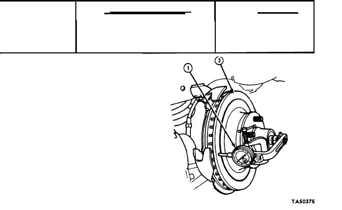
Check lateral runout.
(a)
(b)
(c)
(d)
Install rotor. (See TM 9-2320-
289-20)
Tighten
wheel
bearings to
eliminate freeplay.
Attach dial indicator (1) to some
portion of suspension. Point of
plunger must contact rotor face
(2) about 1 in. (25 mm) from
rotor edge.
Move rotor 1 complete rotation.
Lateral runout should not exceed
0.004 in. (0.102 mm). If lateral
runout
exceeds
0.004 in.
(O. 102 mm), machine rotor.
7-3