TM 9-2320-289-20
11-3.
HEATER CONTROL PANEL MAINTENANCE (Con’t).
1.
2.
NOTE
Each ASSEMBLY step can be performed separately from other ASSEMBLY
steps. Perform only as required.
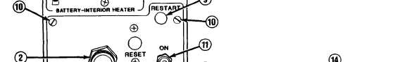
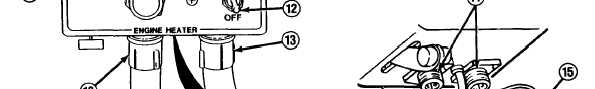
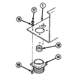
Install grommet (18) if removed.
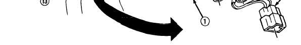
Install receptacle connector (14) on
underside of heater control panel (1)
with 4 screws (19), new Iockwashers
(16), and nuts (17). Repeat for other
receptacle connector if removed.
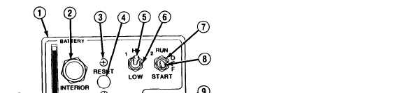
Position toggle switch (5, 8, or 12)
through heater control panel (1) hole
and install with nut (6, 7, or 11). DO
NOT fully tighten nut. Connect leads
to toggle switch and tighten nut.
Install indicator light (9) through
heater control panel (1) hole with
washer and nut. Connect lead to back
of indicator light.
TA50037
11-7