TM 9-2320-289-20
7-7.
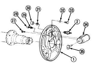
BRAKE SHOE AND WHEEL CYLINDER REPLACEMENT (Con’t).
2.
Install wheel cylinder (34) on backing plate (1) with 2 bolts (27). Tighten bolts to 15 Ib.-ft.
(20 N•m). Install 2 link rods (35), bleeder valve (29), and cap (28) if removed.
NOTE
M1009
DOES
NOT
use
a
Iockwasher (31) with anchor pin
(2).
3.
Install
anchor
pin
(2)
with
new
I o c k w a s h e r ( 3 1 ) a n d n u t ( 3 0 ) if
removed. Tighten nut to 230 Ib.-ft.
(312 N•m).
NOTE
Primary brake shoe (17) has a
shorter lining than the secondary
brake shoe (5), and is always
installed toward front of truck.
4.
5.
6.
7.
8.
9.
10.
11.
C o n n e c t p a r k i n g b r a k e c a b l e to
parking
brake
lever
(3)
if
disconnected.
Install washer (4) on parking brake lever (3) pin. Install secondary brake shoe (5) on parking
brake lever pin. Install clip (6) on secondary brake shoe.
Install pin (18) in backing plate (1) on secondary brake shoe (5) side. Position adjusting lever
(24), adjusting spring (22), and pivot (21) assembly, ensuring that pin (18) is through
secondary brake shoe and adjusting lever hole.
Install pivot (16), spring (15), and hold-down washer (14), turning hold-down washer to lock in
place on pin (18).
Position primary brake shoe (17) and install pin (18), pivot (16), spring (15), and hold-down
washer (14), turning hold-down washer to lock in place.
Install brake shoe guide (7) on anchor pin (2). Install actuating link (20) on pivot (21) and
anchor pin.
Hook adjusting spring (25) on secondary brake shoe (5) and primary brake shoe (17).
With primary brake shoe (17) moved forward, install strut spring (13) and parking brake strut
(8). Ensure that link rods (35) are engaged in secondary brake shoe (5) and primary brake
shoe notches.
TA49668
7-18