TM 9-2320-289-34
6-16.
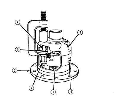
REAR AXLE DIFFERENTIAL REPAIR (M1009) (Con’t),
CAUTION
Ensure that latching bracket (6) spring is pulled out of the way when
removing bushing (4), Failure to follow this caution may result in damage
to governor assembly (7), bushing, or latching bracket spring.
3.
Using bushing remover, remove
bushings (4 and 5). Remove snapring
and spring from latching bracket (6),
and remove latching bracket and
governor assembly (7). Discard
snapring.
NOTE
Axle shaft serves as a tool to help
aline pinion gears (18), camform
side gear (17), and side gear (20).
4.
Place axle shaft in vise with 3 in.
(76 mm) of axle shaft projecting
upwards. Place differential case (2)
assembly on axle shaft.
NOTE
Ensure that all thrust washers (19), shims (11 and 21), pinion gears (18),
clutch packs (13 and 15), and thrust block (23) are marked for assembly in
their original position.
5 .
Remove Iockscrew (9) and pinion shaft (10). Rotate differential case (2) assembly, and
remove 2 pinion gears (18) and thrust washers (19). DO NOT discard Iockscrew. Save for
measuring purposes during assembly.
6 .
Remove thrust block (23). Remove right-hand side gear (20), clutch pack (13 and 15), and
shim(s) (21). Remove left-hand camform side gear (17), cam plate (16), clutch pack (13 and
15), wave spring (14), and shim(s) (11),
TA50591
6-106