TM 9-2320-289-34
6-12.
STEERING KNUCKLE, ARM, AND BALL JOINT MAINTENANCE (M1009)
(Con’t).
NOTE
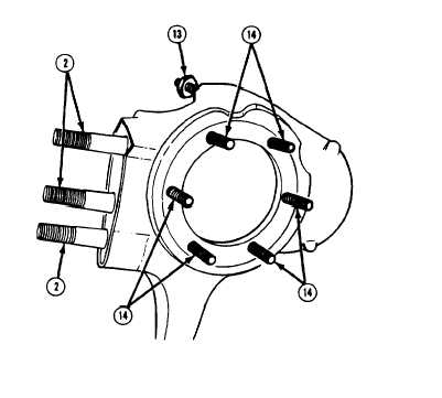
If stop (13) requires replacement,
position and number of exposed
threads should be noted for
installation.
7 .
Inspect 3 steering arm studs (2), 6
spindle bolts (14), and stop (13).
Replace if damaged.
8 .
Inspect upper ball stud adjusting
sleeve (7) at axle housing (6) and
replace if damaged.
b .
ASSEMBLY
l
l
l
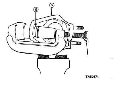
Left
NOTE
side steering knuckle (5), arm, and ball joint (12) assembly is
given,
Ml 009 steering knuckle ball joints (12) do not require lubrication.
Ensure that lower ball joint (12) (ball joint without cotter pin hole In
stud) is straight before it is pressed in place.
1 .
Position new lower ball joint (12) in
steering knuckle (5). Using ball joint
installation
tools
and
adapters
J-23454-2 and J-23454-4, press lower
ball joint into place. Install new
snapring.
2 .
Remove rubber retaining cup from
new upper ball joint (12). Position
upper ball joint at steering knuckle (5)
and install in same manner as lower
ball joint. Install rubber retaining cup
to upper ball joint.
6-80