TM 9-2320-266-34
(2) Remove the
fuel pump (paragraph 23-6).
(4) Remove the clamp, and remove the blower
assembly from the heater.
b. Installation.
(1) Position the blower assembly in the heater, and
tighten the clamp.
23-8. Ventilating Air Blower.
a. Removal.
(1) Disconnect the two electrical Ieads from the
blower assembly.
(2) Loosen the motor support clamp.
(3) Remove the four screws securing the blower
housing to the heater mounting base.
(4) Remove the blower assembly.
b. Installation.
(1) Position the blower assembly, and install the four
attaching screws.
(2) Tighten the motor support clamp.
(3) Connect the two electrical leads.
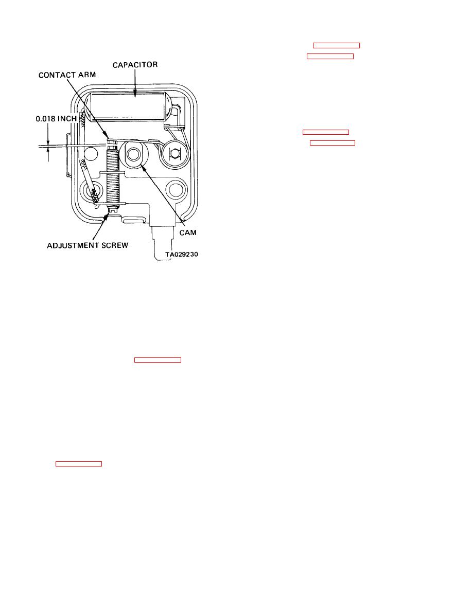
Figure 23-1. Breaker Point Adjustment.
23-9. Heat Exchanger.
(5) Install the attaching screw.
a. Removal.
(6) Adjust the breaker point gap (a, above).
(7) Attach the wires.
(2) Disconnect the control cable from the thermostat
( 8 ) Install the cover.
control switch.
23-6. Fuel Pump.
(3) Disconnect the electrical wires from the switch.
a. Removal.
(4) Remove the thermostat control switch attaching
screws, and remove the switch.
(1) Disconnect the fuel line hoses from the pump.
(5) Remove the overheat switch.
(3) Remove the attaching nuts and remove the pump.
outlet from the extension.
(4) Remove the coupling, connector, and washer.
(7) Remove the heat exchanger assembly.
NOTE
(8) Remove the two screws which secure the
The connector has left-hand threads.
wrapped ends of the housing.
(9) Spread the housing, and remove the heat
b. Installation.
exchanger.
(1) Install the washer, connector, and coupling.
b. Installation.
(2) Position the pump on the motor, and install the
(1) Position the housing on the heat exchanger.
attaching nuts.
(3) lnstall the ignition unit, and adjust the breaker
(2) lnstall the two end screws.
points (paragraph 23-5).
(3) Position the heat exchanger assembly in the
heater.
(4) Connect the fuel Iines.
(4) Connect the heat exchanger exhause tube outlet
23-7. Combustion Air Blower.
to the extension.
a. Removal.
23-2
Change 2


