TM 9-2320-289-34
5-9.
REAR SERVO ASSEMBLY MAINTENANCE (Con’t).
b.
BAND APPLY PIN SELECTION CHECK
1.
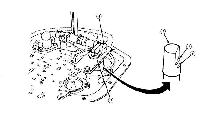
Install pin selector gage (6) over rear servo bore with smaller diameter of gage pin (7) in servo
pin bore and secure with two 5/16 -18 x 1 in. screws tightened to 216 lb.-in. (24 N.m). Ensure
that gage pin is free to move up and down in both pin selector gage and servo pin bore and
that steps (8 and 9) of gage pin and machined surface (10) of pin selector gage are facing
front of transmission case.
2.
Apply 25 Ib.-ft. (34 N.m) to hex nut on side of pin selector gage (6).
NOTE
Identification rings are located on top of servo pin (4).
3 .
Note relation of steps (8 and 9) on gage pin (7) with machined surface (10) on top of pin
selector gage (6) and determine proper size servo pin (4) as follows:
(a) If machined surface (10) on top of pin selector gage (6) is even with or above upper step
(8) of gage pin (7), long servo pin (3 rings) is required.
(b) If machined surface (10) on top of pin selector gage (6) is between upper step (8) and
lower step (9) of gage pin (7), medium servo pin (2 rings) is required.
(c) If machined surface (10) on top of pin selector gage (6) is even with or below lower step
(9) on gage pin (7), short servo pin (1 ring) is required.
4 .
If new servo pin (4) is required, make note of size. Remove pin selector gage (6) and gage pin
(7) from transmission,
TA50232
5-45