TM 9-2320-289-34
F-1.
GAS-PARTICULATE FILTER UNIT (GPFU) INSTALLATION (M1010) (Con’t).
39.
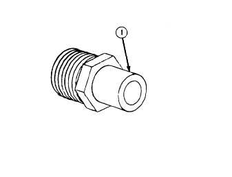
Install 2 brass adapters (1) to fifth tee
for use at cab floor, Install cab tee (9)
assembly to cab floor, just behind
driver’s seat, with tee clamp, screws,
and Iockwashers. Ensure that side
opening of cab floor tee assembly
faces rear cab wall.
40.
Connect 1 end of 6 ft. (1 .83 m) flex
hose to cab tee (9) at upper left
corner of air conditioner in patient
compartment with hose clamp. Feed
flex hose through grommeted hole in
triangular door jam bracket and install
to cab floor tee with hose clamp.
Secure 6 ft. (1 .83 m) flex hose to
wall of patient compartment with hose
wall clamp.
41.
Connect 4 brass adapters (1) to inlet and outlet ends of driver’s and passenger’s heaters.
Plug top inlets and outlets as required.
42.
Remove small bolts behind lower left side of driver’s seat and lower right side of passenger’s
seat. Using removed bolts, install driver’s and passenger’s heaters with inlet sides facing
down,
43.
Install 2 support brackets on cab wall near top and outside of seats with bolts and Iockwashers.
Install 2 orifice assemblies through holes in 2 support brackets and secure with 2 snaprings.
NOTE
Ensure that valve assemblies have been removed from quick disconnects
(24) before installation.
44.
Install 2 quick disconnects (24) to ends of two 2 ft. (0.61 m) flex hoses with 2 hose clamps.
Install other ends of 2 ft. flex hoses to outlets ends of driver’s and passenger’s heaters. Install
2 quick disconnect ends to orifice assemblies at 2 support brackets.
45.
Install 1 end of another 2 ft. (0,61 m) flex hose to inlet end of driver’s heater with hose clamp.
Install other end of same flex hose to cab floor tee with hose clamp.
46.
Install 1 end of 4 ft. (1.2 m) flex hose to inlet end of passenger’s heater with hose clamp.
Feed same flex hose under cab ramp and install to cab tee (9) with hose clamp.
47.
Turn all heaters to “OFF” position.
TA50193
F-13