TM 9-2320-289-34
6-8.
FRONT AXLE DIFFERENTIAL MAINTENANCE (ALL EXCEPT Ml 009) (Con’t).
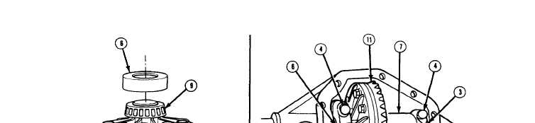
4. Install dial indicator (24) on housing with indicator button contacting back of ring gear (11).
Rotate differential case (7) assembly and check for runout. If runout is greater than 0.002 in.
(0.051 mm), remove differential case assembly from housing, and remove ring gear.
Assemble differential case assembly without ring gear and install in housing,
5. Check runout at ring gear mounting flange (23). If runout on flange exceeds 0.002 in.
(0.051 mm), problem is probably in side bearings (9) or differential case (7) and must be
corrected before proceeding. If runout is within specifications, problem is with ring gear (11).
Install ring gear, ensuring that ring gear bolts (8) are tightened evenly and ring gear mounting
flange is free from dirt or chips, etc. Recheck runout with dial indicator (24) contacting back of
ring gear. If runout is still greater than 0.002 in. (0.051 mm), replace ring gear, ring gear
bolts, and drive pinion as a set.
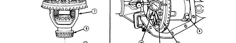
6. Using 2 screwdrivers wedged between bearing cup (6) and housing on opposite side of ring
gear (11 ) (away from dial indicator (24) side), force differential case (7) assembly as far as
possible toward dial indicator. Rock ring gear to set bearings, With force still applied, set dial
indicator to “0, ”
7. Reposition 2 screwdrivers between bearing cup (6) and housing on ring gear (11) side. Force
differential case (7) assembly as far as possible in opposite direction. Repeat several times
until the same reading is obtained. Record reading. This reading is the total thickness of
shim (s) needed, less preload, for setting backlash and preload during assembly.
8. Remove 4 bearing cap bolts (4) and 2 side bearing caps (3). Remove differential case (7)
assembly from housing,
TA50545
6-51