TM 9-2320-289-34
5-21.
TRANSFER CASE MAINTENANCE (ALL EXCEPT M1028A1 AND M1031)
(Con’t).
NOTE
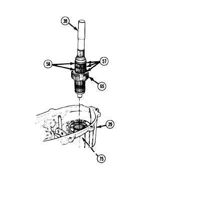
Mainshaft (39) should be placed in a soft-jawed vise while assembling
spacers (57) and roller bearings (58).
1
7 .
Lightly coat mainshaft (39) with
petrolatum and install first spacer
(57). Install first row of 60 roller
bearings (58). install second spacer,
then second row of 60 roller bearings.
Install third spacer. Lightly coat
outside surfaces of all roller bearings
with petrolatum to ensure that they
remain in position.
NOTE
Before installing mainshaft (39),
ensure that input drive gear thrust
bearing (75) is properly centered
in
input
drive
gear.
(See
ASSEMBLY, step 11)
18.
Install
mainshaft
(39)
and
synchronizer hub (65) in front case
(29) .
NOTE
Transfer cases manufactured before July 1, 1983 (as stamped on
identification plate) have no straight pin.
19.
Lightly coat straight pin with petrolatum and install to mainshaft (39).
20.
Install mode fork retainer (62) to mode fork (63). install mode fork to synchronizer sleeve (64)
with flat side of synchronizer sleeve facing front of front case (29),
21.
Install mode fork (63) and synchronizer sleeve (64), as a unit, to shift rail (47), engaging teeth
of synchronizer sleeve with teeth of synchronizer hub (65),
22.
Install front output shaft (33) front thrust bearing assembly with thick thrust washer (61 ) next to
front case (29), followed by thrust bearing (60), and thin thrust washer (59). Install front output
shaft.
TA50326
5-152