TM 9-2320-289-34
3-42.
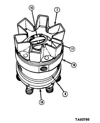
FUEL INJECTOR PUMP HYDRAULIC HEAD MAINTENANCE (Con’t).
3.
Remove rotor (16) assembly from
roller testing fixture (20), Holding
rotor
assembly at base,
install
delivery valve (24), spring (26), and
new delivery valve stop (27) with
screw (28).
NOTE
Ensure that rollers (19) and shoes
(23) remain in their slots when
installing rotor (16) assembLy in
roller testing fixture (20).
4.
Connect air hose (22) to air inlet hole
in roller testing fixture (20), and
supply 40-100 psi (276-690 kPa) of
compressed
air.
Install
rot or
assembly in roller testing fixture on air
inlet side.
5.
Check dimension between between rollers (19). Dimension should be 1.9765-1.9775 in.
(50.203-50.229 mm). Adjust leaf spring screw (21) until proper dimension is obtained.
Disconnect air hose (22) from air inlet hole.
NOTE
Ensure that rollers (19) and shoes
(23) remain in their slots when
installing rotor (16) assembly in
hydraulic head assembly (10).
6.
Install
rotor
(16) assembly in
hydraulic head assembly (10).
NOTE
When installing cam ring (8),
ensure that arrow on cam ring is
pointing clockwise and that notch
on cam
ring faces front of
hydraulic head assembly (10).
7.
Install cam ring (8) on hydraulic head
assembly (10). Install weight retainer
hub (18) and weight retainer (7) on
cam ring. Install snapring (17) on
rotor (16).
3-153