
TM 9-2320-280-34
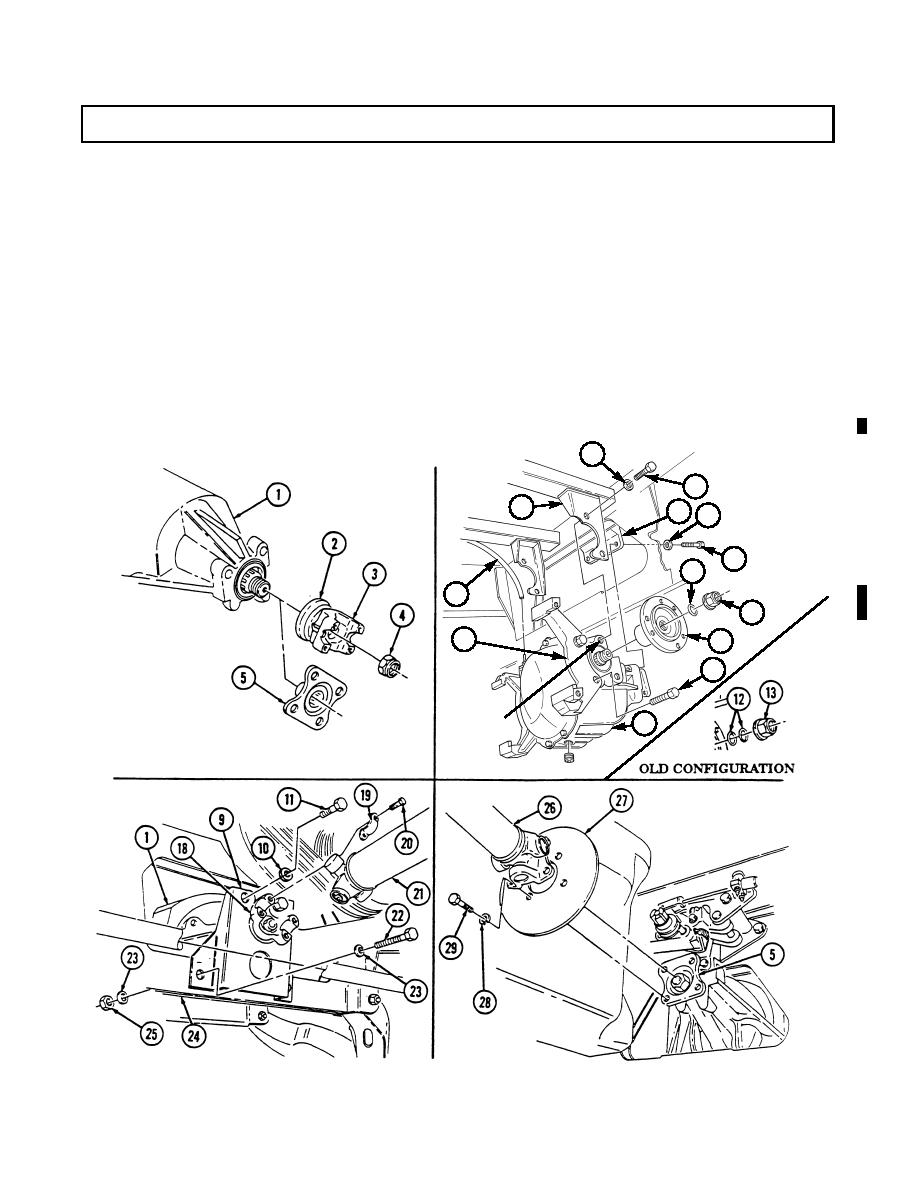
9-5. DIFFERENTIAL REPLACEMENT (Cont'd)
12.
Tighten capscrews (8) and (11) to 110-140 lb-ft (149-190 Nm).
NOTE
Perform steps 13 and 18 if replacing front or rear differential
on vehicles with serial numbers USBL Eff. 44825 and above.
Perform steps 14 through 18 if replacing rear differential on
vehicles with serial numbers USBL Eff. 44825 and below.
13.
Connect propeller shaft (21) to pinion yoke (18) with two straps (19) and four capscrews (20).
Tighten capscrews (20) to 13-18 lb-ft (18-24 Nm).
14.
Remove locknut (4) and pinion yoke (3) from service differential (1).
15.
Install pinion flange (5) and locknut (4) on service differential (1).
16.
Tighten locknut (4) in small increments, until torque required to rotate pinion flange (5) exceeds
original measurement (step 1) by 2 lb-in. (0.2 Nm).
17.
Install parking brake rotor (27) and connect propeller shaft (26) to pinion flange (5) with four
capscrews (29), and lockwashers (28). Tighten capscrews (29) to 60 lb-ft (81 Nm).
18.
Install two output flanges (14), O-rings (12), and two locknuts (13). Tighten locknuts (13) to
165-195 lb-ft (224-264 Nm).
7
8
6
9
10
11
12
17
13
16
14
15
TAPPED
1
HOLES
FOLLOW-ON TASKS: Install service brake rotors (TM 9-2320-280-20).
Fill differential to proper level (TM 9-2320-280-20).
Change 2
9-9

